As an engineer, it is important to have a clear guideline to follow when going through the design process. Below, you can find a representation of my personal engineering design process – what I’ve come to call the “Shell Process”:
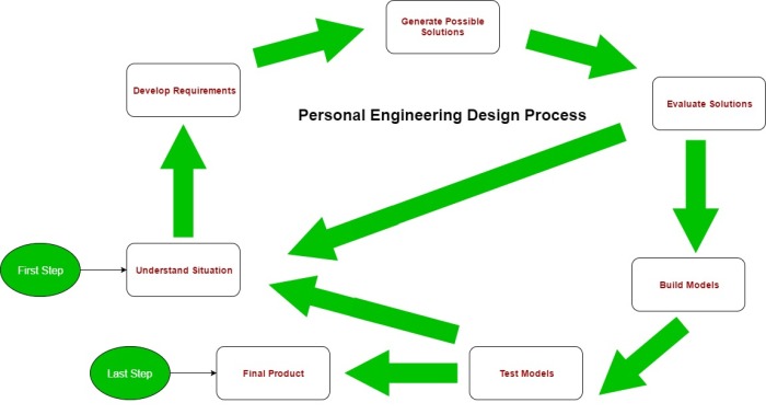
Figure 1. Shell Process represented as a flow chart.
Understand Situation
This involves doing primary and secondary research to be able to identify and fully understand the opportunity, including speaking to stakeholders and conducting library research.
Develop Requirements
Requirements will be the basis upon which an engineer builds designs, thus it should be done early on. Requirements include identifying objectives, metrics, constraints, and criteria.
Generate Possible Solutions
Produce as many possible solutions as possible to the opportunity identified in Understand Situation. Brainstorming and reference designs may be used in this step.
Evaluate Solutions
Once solutions have been generated, they should be evaluated against the requirements developed in Develop Requirements to determine which solutions are possible long-term solutions. This may also involve relative comparisons of the solutions, such using a Pugh Chart, or validating that the designs suffice and verifying with stakeholders. Some people to go to for advice in this stage include experts in the field that is being evaluated.
Reiterate
After evaluating solutions, one can go forward to Build Models or go back to Understand Situation. Based on the results of evaluating the solutions, one may need to readjust the understanding of the opportunity, thus causing another iteration of the cycle. This can happen as many times as needed until satisfactory solutions have been developed.
Build Models
Once one is satisfied that the solutions that have are decent, it is the time to create prototypes for the best solutions that have come from previous evaluations.
Test Models
What are models for if not to help one gain insightful information? Verify that the solution(s) work and are effective by using the models in the field. Use these results to narrow down to one final solution.
Reiterate
Again, one should re-adjust based on new information if needed.
Final Product
Now that the final solution is chosen, it is time to implement it and produce a product one can be proud of. Done!
A Note on the Shell Process:
This process was named as such due to the shell-like shape it resulted in when presented as a flow chart (Figure 1). This process was adapted from the “Waterfall Methodology” (Figure 2) (Glushko, 2017) and “Iterative Design Process” and based off previous experience with the FDCR Design Process introduced in ESC101 (Figure 3) (Irish & Foster, 2016). The Waterfall Methodology is based on one step leading to another (hence the sequential nature of the Shell Process) while the Iterative Design Process indicates that the design process must be repeated multiple times (thus the loops in the cycle) (Glushko, 2017).
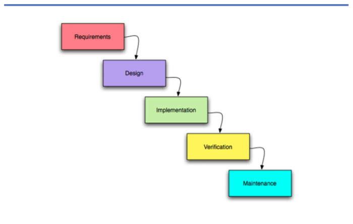
[1] Figure 2. Waterfall Methodology
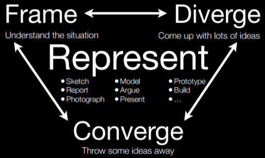
[2]Figure 3. FDCR Design Process
[1] Source of image: http://courses.ischool.berkeley.edu/i290-1/f08/lectures/ISSD-20080917.pdf
[2] Source of image:
Click to access ESC101%2020169%20Lecture%2009%20Actual.pdf
Sources Cited
Glushko, B. (2017). 6. Models of Design Process. Retrieved 25 February 2017, from http://courses.ischool.berkeley.edu/i290-1/f08/lectures/ISSD-20080917.pdf
Irish, R. & Foster, J. (2016). ESC101 20169 Lecture 09 (2nd ed., p. 13). Toronto. Retrieved from https://design.engsci.utoronto.ca/courses/esc101/20169/ESC101%2020169%20Lecture%2009%20Actual.pdf
